| 1 |
OSAW Regulated Power Supply Using Zener Diode
Technical Specifications
(i) 12 Volt AC Step down Transformer
(ii)Four IN4007 rectifier Diodes
(iii) Electrolytic Capacitances 100µF and 220µf
(iv) Load Resistance Band Switch (RL =R×100) i.e.,100O to 1000O
(v) Zener Diodes 5.1V , 6.2V , 10V
(vi) Two Digital Voltmeters and one Ammeter fixed on the front Panel
(vii) Connecting Leads
(viii) Instructional Lab Manual
|
|
| 2 |
Transistor Characterstics
Experiment:- To study the characteristics of PNP/NPN transistor .
Technical Specifications:
OSAW Transistor Hybrid Parameter Apparatus consists of:
(i) Two Regulated DC Power supplies of 0 -1.5 Volts and 0 - 10Volts
(ii) Two Analog Ammeters
(iii) Two Analog Voltmeters
(iv) PNP/NPN Transistor (SK-100/SL-100)
(v) Connecting leads.
(vi) Circuit diagram is engraved on a milky Acrylic sheet
|
|
| 3 |
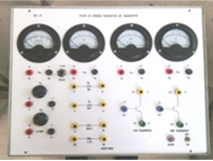
Hybrid Parameters of Transistor
Experiment:-To study the characteristics and Hybrid Parameters of PNP/NPN
transistor in common base configuration
Technical Specifications: -
OSAW Transistor Hybrid Parameter Apparatus consists of:
(i) Two Regulated DC Power supplies of 0 -1.5 Volts and 0 - 10Volts
(ii) Two Analog Ammeters
(iii) Two Analog Voltmeters
(iv) PNP/NPN Transistor(SK-100/SL-100)
(v) Connecting leads.
|
|
| 4 |
PN junction diode, and Light emitting diode Characterstics Apparatus
Experiment: To study V-I Characteristics of PN junction diode, and Light emitting diode.
Technical Specifications:
PN –Junction diode and LED Trainer kit consists of:
(1) Dual regulated DC Power Supply 0-1.5V and 0 -200V.
(2) Germanium and Silicon diodes and LEDs
(3) Analog Voltmeter of dual range (2V/200V) and Analog Ammeter of dual range (100µA /15 mA)
(4) 4mm patch cords
(5) Instructional Lab Manual
(6) Circuit diagram is engraved on the Milky White Acrylic sheet .
(7) Mains Power Supply: 230Volts/50Hz.
|
|
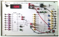
| 5 |
OSAW Digital to Analog(DAC) & Analog to Digital(ADC) conversion Apparatus
Technical Specifications:
OSAW Digital to Analog(DAC) Analog to digital Conversion(ADC) Apparatus
(i) Digital Voltmeter to measure the applied input voltage.
(ii) 8 Bit binary inputs(High –low switches) with LED indicators
(iii) 8 Bit binary outputs with LED indicators
(iv) Inbuilt +5V variable DC power supply
(v) IC DAC- 800 and ADC-804
(vi) Circuit diagram is engraved on a milky Acrylic sheet
(vii) Connecting leads.
|
|
| 6 |
Operational Amplifier Apparatus
Experiment:- To Study the Operational Amplifier.
Technical Specifications:
OSAW Operationall Amplifier Apparatus consists of:
(i) Dual Regulated DC Power supply of ±12 Volts
(ii) Inbuilt Function Generator(30Hz to 100KHzfrequency) .
(iii Analog Voltmeter to measure the input and output voltages
(iv) Three Op-Amp IC –741
(v) On Board Four Band switches for Resistances
(vi) Output Banana connectors for C.R.O connections
(vii)Circuit diagram engraved on a Milky Acrylic Sheet
(viii) Patch-cords
|
|
| 7 |
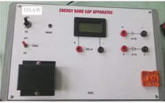
OSAW Energy Band Gap Apparatus
Technical Specifications:
Energy Band gap apparatus consists of:
(i) Regulated DC. Power supply of 2Volts/10mA
(ii) Digital Micro-ammeter of 200µA DC
(iii) Semiconductor Diode(IN-34)
(iv) Oven to heat the semiconductor diode
(v) Thermometer (0-1100C)
(vi) Patch cords
|
|
| 8 |
OSAW LCR - Impedance Apparatus
Technical Specifications:
OSAW LCR –Impedance apparatus consists of:
(i) OSAW LCR-Impedance Apparatus that comprise
(a) 0-15 Volt AC supply with AC Voltage Adjust Pot.
(b) 15 Volts AC Voltmeter and 200mA Ammeter on board
(c) A set of Three Inductances(50mH ,100mH,200mH)
(d) A set of Three Capacitors(10µf ,47µf ,100µf)
(e) A set of Three Resistances(100O ,200O ,500O)
(ii) Patch Cords for Circuit Connections
(iii) Circuit diagram engraved on Milky Acrylic Sheet.
|
|
| 9 |
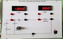
OSAW Tunnel Diode Characterstics Apparatus
Experiment :To show the tunneling effect in tunnel diode using I-V characterstics
Technical Specifications:
The Trainer Kit Consists of the following Specifications:
(i) Regulated DC Power supply of +5 Volts.
(ii) Two Digital Panel Voltmeters : V1 and V2 (Range 0- 2V DC).
(iii) Current control Potentiometer on the Front Panel of the Trainer module.
(iv) Tunnel Diode –IN 3717.
(v) Circuit diagram engraved on Milky Acrylic Sheet
(vi) Patch Cords
(vii) Instructional Lab Manual
|
|
| 10 |
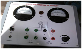
Ionization potential of mercury Apparatus
Experiment :To determine the ionization potential of mercury.
Technical Specifications :
The Instrument comprises the following built in parts
(i)Regulated DC Power supply (0-15 Volts )
(ii)AC Power supply (6.3 Volts)for filament
(iii)One Digital Panel Voltmeter(0-15V)
(iv)One Digital Panel Ammeter(0-30mA)
(v)Mercury Valve(2D21) mounted on valve base fixed on front panel.
(vi)Patch Cords
|
|
| 11 |
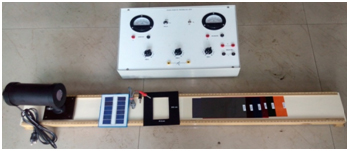
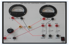
OSAW Solar- Cell characteristics
Experiment: - To study the photovoltaic cell characteristics as:
- V-I characteristics of photovoltaic cell. switch on the apparatus
- Spectral characteristics of photovoltaic cell.
- Areal Characteristics of photovoltaic cell.
Technical Specifications:
- Light source Tungsten Bulb (60W/100W) mounted on a Bakelite base
- Solar cell (6Volt/150mA).
- Solar cell stand fitted on a Bakelite base.
- Experimental module kit.
- Wooden bench with 100cm. scale.
Main features of the experimental apparatus as given below:
-
Two analog dual range meters are given on the front panel as given below:
Voltmeter - (1Volt. /10 Volt.) and Ammeter – (10mA. / 100mA).
And connections are brought out on the 4mm sockets for input and output connections.
-
Three nos. of variable resistances as mounted on the band switch given on the front panel in series.
1×1000O, 1×100 O, 1×10 O and connections brought out on the 4mm. sockets.
- Two pair of 4mm banana sockets also given on the front panel to connect the solar cell.
- 8 nos. of color filters also provided with the apparatus.
- Chopper plates with different window size given with this experiment
|
|
| 12 |
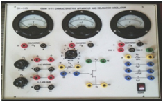
UJT Characterstics Apparatus
(CAT. No. : CH-5(O)
Experiment : Study of UJT Characterstics and UJT as a relaxation Oscillator
Technical Specifications:
(i) Inbuilt Dual DC Power Supply(0-15V)
(ii) Two Analog Voltmeter(0-10 V and 0-15V) on the front panel.
(iii) One Analog Meter (0-25mA)
(iii) One Band Switch (R × 5KO) of variable resistances(5KO to 50KO)
(iv) UJT 2646
(v) Resistances and Capacitances according to Circuit design
(vi) Patch cords
(vii) Instructional Lab Manual
|
|
| 13 |
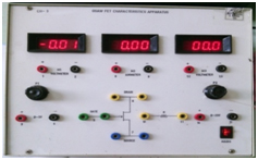
FET Characterstics Apparatus(CAT. No. : CH-3)
Experiment: To study the Output and Transfer Characterstics of A FET
Technical Specifications:
(i) Inbuilt Dual DC Power Supply(0-5V) and (0-25V)
(ii) Two Analog Voltmeter on the front panel.
(iii) One Analog Meter (0-10 mA)
(iii) Two Variable resistances for voltage adjustment of both power supplies
(iv) FET BFW-10
(v) Resistances according to Circuit design
(vi) Circuit diagram engraved on a milky white Acrylic sheet
(vii) Patch cords with 4mm banana plug
(ix) Instructional Lab Manual
|
|
| 14 |
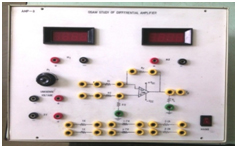
OSAW Differential Amplifier Apparatus (CAT. No. : AMP-8)
Experiment:- To Study the Differential Amplifier.
Technical Specifications:
OSAW Differential Amplifier Apparatus consists of:
(i) Regulated DC Power supply of 3.0 Volts
(ii) Regulated and Variable DC Power supply of (0 -15)Volts indicated
as (Un-known Voltage) .
(iii) Digital Voltmeters to measure the input and output voltages
(iv) Op-Amp IC –741
(v) Circuit diagram engraved on a Milky Acrylic Sheet
(iv) Patch-cords
|
|
| 15 |
PN junction diode Characterstics Apparatus(CAT. No. : CH-13)
Technical Specifications:
(1)Dual regulated DC Power Supply 0-1.5V and 0 - 200V.
(2) Germanium and Silicon diodes
(3) One Digital Voltmeter and one Digital Ammeter
(4) Connecting Banana leads 4mm
(5) Instructional Lab Manual
(6) Circuit diagram is engraved on the Milky White Acrylic sheet
|
|
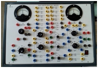
| 16 |
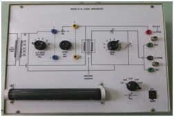
Study Of Zener diode regulating characterstics
(CAT. No. : CH-14)
Technical Specifications:
(1) Regulated DC Power Supply 0 -12V with a variable potentiometer.
(2) Zener diodes(5.1V, 6.2V ,10V)
(3)Two AnalogVoltmeters and one Analog Ammeter
(4) One band switch of Load resistances(R×100O) is fixed on the Front panel .
(5) Connecting Banana leads 4mm
(6) Instructional Lab Manual
(7) Circuit diagram is engraved on the Milky White Acrylic sheet
|
|
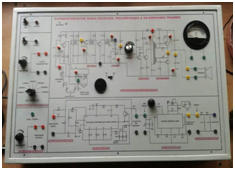
| 17 |
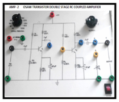
RC- Coupled double stage Amplifier
(CAT. No. : AMP-2)
Experiment: To calculate the voltage gain and to observe frequency response of RC Coupled
amplifier.
Technical Specifications:
1. OSAW RC-Coupled Amplifier Apparatus consists of:
(i)Inbuilt Function generator circuit having frequency 30Hz – 100KHz and Amplitude Variation using Potentiometer
(ii)Inbuilt DC Power Supply (±12Volts)
(iii)Band Switch for different frequencies selection
(iv)Band switch for different load resistances (20KO ,40KO ,60KO ,80KO, 100KO, 120KO, 140KO)
(v) Two Transistors BC-107
(vi)Resistances, Capacitances according to design
(vii)4mm Patch Cords
|
|
| 18 |
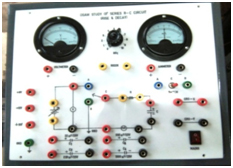
Experiment: To study Rise and Decay in a Seies RC- Circuit
Or
To study Characterstics of Series RC –Circuit.
Technical Specifications:
(1) Osaw Characterstics of Series RC-Circuit apparatus that has
(a) inbuilt DC regulated supply of +9V ,+12V , +15V.
(b) Analog Voltmeter of 0- 20 volt and Moving Coil Galavanometer of 1A- 0-1A range are
mounted on the Front panel of the apparatus.
(c) A decade Resistance Band Switch and a set of Four Capacitances470µf,1000µf,2200µ
and 4700µf are connected inside and connections are brought out at terminals
provided on the front panel.
(d) Two way toggle Switch
(2) Stop Watch
(3) Output Connection for C.R.O
(4) 4mm Patch Cords
(5) Circuit Diagram engraved on a white Milky Acylic sheet
(6) Mains Power Supply:230V/50Hz
|
|
| 19 |
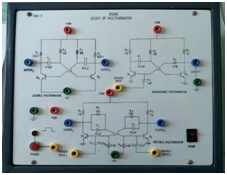
OSAW Study of Multivibrator using Transistors
Technical Specifications: (1) Osaw Multivibrators apparatus has
(a) inbuilt DC regulated supply of +12V
(b)Inbuilt Pulser Circuit as a clock
(c) Transistors ,Resistors and Capacitors according to circuit design
(d)Connecting Leads
(e) Instructional lab manual
|
|
| 20 |
B-H Curve Apparatus
(CAT. No. : BH-3)
Technical Specifications:
OSAW B-H Curve apparatus consists of:
(i) 12 Volt AC supply with AC Voltage Adjust Pot.
(ii) A Specimen Step down Transformer
(iii) A Band Switch having a set of Five Capacitors(1 µf ,2 µf,3 µf ,4µf ,5µf)
(iv) A Band Switch(R×10K) having a set of Five Resistances(10KO to100KO)
(v) Patch Cords with 4mm babana plug for Circuit Connections
(vi) Output Terminal for X and Y terminals of Oscilloscope
(vi) Circuit diagram engraved on Milky Acrylic Sheet.
|
|
| 21 |
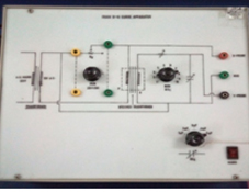
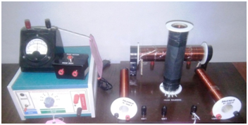
Study of B-H Hysteresis curve(Ferromagnetic material)
Experiment:- Study of B-H Hysteresis curve for given ferromagnetic material
Technical Specifications:
(1) OSAW B-H Hysteresis Curve Apparatus that consists of:
(a) 2,4,6,8,10 ,12 Volts variable AC Power Supply inbuilt with selector switch
(b) Potentiometer(P1/RH) of 25O/3W on the front panel
(c) Band Switch(BS1) having resistances of (R×10kO) on the Front Panel
(d) Band Switch(BS2) having capacitances of (0.1µf ,0.2µf , 0.3µf ,0.4µf 0.5µf ) on the Front panel
(e) Two output BNC connectors marked X-Probe and Y-Probe for CRO connections.
(2) A Solenoid is mounted on the front panel having Primary(280 Turns)and Secondary Coil(10000Turns.)
(3) Different material Thin Metal wires of same length and different diameters are provided.
|
|
| 22 |
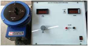
Boltzmann Constant Experiment
Experiment: To determine the Boltzman Constant using a Semiconductor diode.
Technical Specifications:
- Trainer kit having Digital voltmeter and ammeter
- Regulated DC Power Supply 0-5V
- Germanium Diode
- Heating Oven with Hylum sheet cover
- Thermometer(0-110°C)
- Connecing leads
- Lab Manual
|
|
| 23 |
Faraday’s Law
Experiment: To verify Faraday and Lenz’s law of electromagnetic induction
Technical specifications:
(i)Regulated 2-12V/2A Power Supply
(ii) Galavanometer( 30-0-30µA)
(III)Micro-Switch
(iv)Solenoid having three windings of 400,600 and 800 turns fixed on a wooden base
(v)Solenoid having Primary and secondary coils of 400 and 500 turns fixed on a wooden base
(vi) Solenoid of 300 and 500 turns.
|
|
| 24 |
OSAW Work function Apparatus
Experiment :Work function of material of filament of directly heated vacuum diode.
Technical Specifications:
The Instrument comprises the following built in parts:
- Regulated DC Power supply (0-200 Volts )Variable.
- DC Current source (0 -3 Amp /12 Volts)for filament
- Two Digital Voltmeter to measure the anode voltage and Filament voltage of the Vacuum diode..
- One Digital Ammeter to measure the current through the filament of the Vacuum diode.
- One Digital milli-ampere Ammeter to measure the Anode Current of the Vacuum diode.
- Vacuum Diode mounted on valve base fixed on front panel.
- Patch Cords
|
|
| 25 |
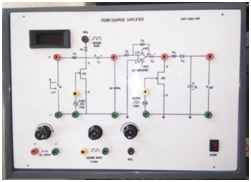
OSAW Chopper Amplifier
(CAT.No. : CHA-918)
Technical Specifications:
(i) Inbuilt Regulated DC Power supply of +1.5Volts and ±12Volts
(ii) JFET as a Modulator and De-modulator
(ii) Inbuilt Square wave generator of 1KHz as a clock for FET gate
(iv) IC 741 Op-amp for Chopped wave Amplification
(v) Diode IN-4007 for compensation and peak detection
(vi) Null setting using a square wave
(vii) Connecting Leads
|
|
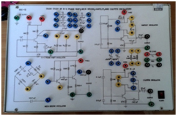
| 26 |
OSAW Oscillators Apparatus
(CAT. No. OSC-12)
Experiment : To study the R-C Phase shift,Wein Bridge,Hartley and Colpitt Oscillators.
Technical Specifications:
(i) Inbuilt Regulated 12V DC Power supply
(ii)Transistor CIL 531 and 2N2219
(iii) Resistances ,Capacitances and Inductances according to circuit design
(iv) Circuit diagrams engraved on a Milky Acrylic Sheet
(v) 4mm Banana sockets are provided for Output CRO connections.
(vi)Patch cords
(vii) Instruction manual
|
|
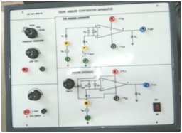
| 27 |
Analog Comparators
Experiment: Study of Inverting and Non-Inverting Comparator Circuits
Technical Specifications:
OSAW Differential Amplifier Apparatus consists of:
(i) Regulated DC Power supply of 0-5 Volts for reference voltage.
(ii) Inbuilt frequency generator(1Hz to 10KHz)
(iii) Regulated Dual DC Power supply of ±12 Volts.
(iv) Digital Voltmeter to measure the reference voltage.
(v) Two Op-Amp ICs –741
(vi) Two BNC Output connector for C.R.O connections.
(v) Circuit diagram engraved on a Milky Acrylic Sheet
(iv) Patch-cords
|
|
| 28 |
Experiment :To verify the Thevenin and Norton theorems
Technical Specifications:
(i) DC Voltage sources: Two Voltage sources of 2 Volts and 6 Volts
(ii) Current sources : Two current sources of 25mA
(iii)Two Digital Voltmeters and two digital ammeters
(iv) Four Band switches of Impedances
(v)Four band switches of admittances
(vi) On board circuit connectors using 4mm banana plug.
(vii) Connecting leads
(viii) Circuit diagram is engraved on the Milky White Acrylic sheet
(ix) Instructional Lab Manual
|
|
| 29 |
Experiment :To verify the Superposition, and Maximum power transfer theorems
Technical Specifications:
(i) DC Voltage sources: Two Voltage sources of 5 Volts and 12 Volts
(ii) One Digital Voltmeter20V
(iii)Three digital ammeters(200 mA ,100 mA ,100 mA)
(iv) Three Band switches of Resistances(R×10O ,R×100O , R×100O.
(v) On board circuit connectors using 4mm banana plug.
(vi) Connecting leads
(vii) Circuit diagram is engraved on the Milky White Acrylic sheet
(viii) Instructional Lab Manual
|
|
| 30 |
Experiment : To calibrate Resistance Temperature Device(RTD) using Null method/Off balance bridge.
Technical Specifications:
(1) Wheat stone bridge with differential amplifier Apparatus that has inbuilt DC
supply ±12 Volts inbuilt.
(2) Resistance Temperature Detector(RTD)
(3) Hot water Pot and Cold water Pot
(4) Thermometer 210oC
(5) Connecting Leads
|
|
| 31 |
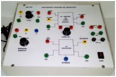
Communication-Lab Experimental Trainer kits Details
Frequency modulation and Demodulation Apparatus
(CAT. No. : FM-16)
Technical Specifications:
OSAW Frequency modulation and Demodulation Trainer kit that consists of
(i) Inbuilt Career frequency generator using IC XR-2206
(ii) Inbuilt Information(message) Signal generator using IC- 8038 having frequency range 600Hz to 9.0
KHz with amplitude adjusted upto 2.4V
of Sine,Triangular,Square waveforms..
(iii) Inbuilt Regulated Power Supply ±5V ,±15V DC.
(iv) Message Amplitude,Carrier adjust and Frequency Adjust potentiometers
are given on the front panel of the trainer kit
(v) Circuit diagram engraved on a milky white Acrylic sheet
(vi) Patch cords with 4mm banana plug
(vii) Instructional Manual
|
|
| 32 |
Experiment :To generate the DSB-SC Modulated wave and to observe the phase reversal at the zero crossing of the modulating signal.(MOD-13)
Technical Specifications::
- Trainer kit that has inbuilt Modulator and De-modulator circuit using IC 1496 Wide frequency response up to 100 MHz and Internal power dissipation – 500mw(MAX)
- CRO 30MHz or Above
- Inbuilt Function Generator 100KHz
- Regulated Power Supply 0-12V, 500mA
- Patch Cords
- Instructional manual
|
|
| 33 |
Experiment: To generate the SSB-SC Modulation and Demodulation. (MOD-14)
Technical Specifications::
- Trainer kit that has inbuilt Modulator and De-modulator circuit IC 1496 Wide frequency response up to 100 MHz
Internal power dissipation – 500mw(MAX)
- CRO 30MHz or Above
- Inbuilt Function Generator and Audio Frequency Generator
- Regulated Power Supply 0-12V, 500mA
- Patch Cords
- Instructional manual
|
|
| 34 |
Experiment:To study the functioning of Pre-Emphasis and De-Emphasis circuits.
(MOD-15)
Technical Specifications:
(i) Trainer kit that has inbuilt of Pre-Emphasis and De-Emphasis circuits using IC – 741
(ii) Resistors , Capacitors
(iii) Inbuit Function Generator of 100 KHz
(iv) CRO – 30 MHz or Above
(v) DC power supply 15V/500mA
(vi) Patch Cords
(vii) Instructional manual
|
|
| 35 |
Experiment:To generate Pulse amplitude modulated(PAM) signal and demodulate it. (MOD-16)
Technical Specifications:
(i) PAM Trainer kit that has inbuilt Modulator and De-modulator circuit.
(ii) Inbuit Function Generator of 100 KHz and Carier Generator of 400KHz
(iii) CRO – 30 MHz or Above
(iv) DC power supply 12V/500mA
(v) Patch Cords
(vi) Instructional manual
|
|
| 36 |
Experiment:To generate Pulse Positon modulated(PPM) signal and demodulate it. (MOD-17)
Technical Specifications::
(i) PPM Trainer kit that has inbuilt Modulator and De-modulator circuit
(ii) Inbuit Function Generator of 100 KHz
(iii) CRO – 30 MHz or Above
(iv) DC power supply 12V/500mA
(v) Patch Cords
(vi) Instructional manual
|
|
| 37 |
Experiment: To generate Pulse Width modulated (PWM/PTM/PLM/PDM) signal and demodulate it. (MOD-18)
(i) PWM Trainer kit that has inbuilt Modulator and De-modulator circuit.
(ii) Inbuit Function Generator
(iii) CRO – 30 MHz or Above
(iv) DC power supply 12V/500mA
(v) Patch Cords
(vi) Instructional manual
|
|
| 38 |
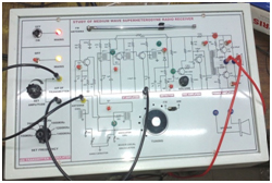
Experiment:To Study the Characterstics of a Superheterodyne Radio Receiver.
Also observe the effect of Pre-Emphasis and De-emphasis.
|
|
| 39 |
Experiment: Study of Medium Wave Superheterodyne Radio Receiver
|
|
| 40 |
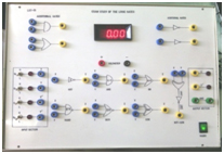
DIGITAL ELECTRONICS LAB APPARATUS
OSAW Study of Logic Gates
(CAT. No. – LGT-16)
Technical Specifications:
(i) Inbuilt Regulated DC +5V power supply
(ii) ICs 7404(NOT) ,7408(AND),7432(OR),7486(EX-OR) Gate
(iii) IC 7400(NAND) and 7402(NOR) Gate
(iv) Digital Voltmeter
(v) Four binary inputs(Low & High) toggle Switches with LED indicators
(vi)Eight Output 4mm banana sockets with LED indicators on the front panel
(vii) Connecting Leads
(viii) Instructional Manual
|
|
| 41 |
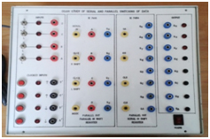
OSAW Serial and Parallel Switching Of Digital Data Apparatus
(CAT. No. :- SPD-18)
Technical Specifications:
(i) Inbuilt Regulated DC +5V power supply
(ii) ICs 7495 and 74164
(iii) IC 7405 for Clock Circuit
(iv) Four binary inputs(Low & High) toggle Switches with LED indicators
(v) Two High and two low Clock signals available on the apparatus front panel
(vi)Eight Output 4mm banana sockets with LED indicators on the front panel
(vii) Connecting Leads
(viii) Instructional Manual
|
|
| 42 |
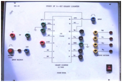
OSAW Study of 4-bit Binary counter
Technical Specifications:
(i) Inbuilt Regulated DC +5V power supply
(ii) ICs 7493
(iii) Inbuilt 1KHz Clock Circuit
(iv) Four binary outputs(Low & High) LED indicators
(v) Circuit diagram engraved on an acrylic white sheet
(vi) Connecting Leads
(viii) Instructional Manual
|
|
| 43 |
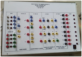
OSAW Binary, MOD-6 ,Decade Counters and Shift Registers Apparatus
( CAT. No. – CNT/SR -19)
Technical Specifications:
(i) Inbuilt Regulated DC +5V power supply
(ii) ICs 7490 ,7493 ,7495 and 74164
(iii) IC 7405 for Clock Circuit
(iv) Four binary inputs(Low & High) toggle Switches with LED indicators
(v) Two High and two low Clock signals available on the apparatus front panel
(vi)Eight Output 4mm banana sockets with LED indicators on the front panel
(vii) Connecting Leads
(viii) Instructional Manual
|
|
| 44 |
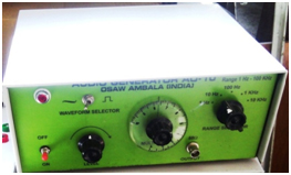
OSAW Audio Signal Generator
(CAT. No. : AO-10)
Technical Specifications:
(i)Frequency Range : 1Hz -100KHz
(ii)Output Impedance : 50O
(iii)Output Waveforms : Sine Wave and Square Wave
(iv)Maximum Amplitude : (i) 8.0 Volts Sine Wave Amplitude
(ii) 10.0 Volts Square Wave Amplitude
(v)Frequency Selector Switch : 1Hz ,10Hz, 100Hz , 1KHz and 10KHz
(vi)Frequency Multiplier Dial : 1 to 10
|
|
| 45 |
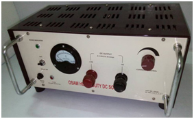
OSAW Heavty duty DC Source(0-3V/25A)
|
|
| 46 |
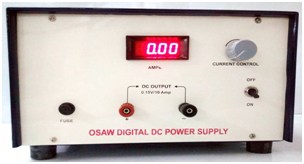
OSAW Digital DC Power Supply(15V/10A)
|
|
| 47 |
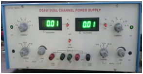
OSAW Dual Channel DC Power Supply(32V/2A)
|
|
| 48 |
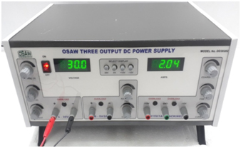
OSAW Three Output DC Power Supply
|
|