| 1 |
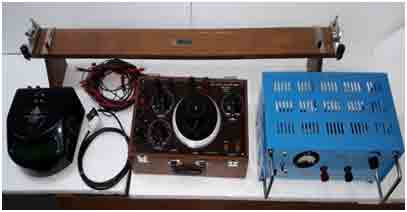
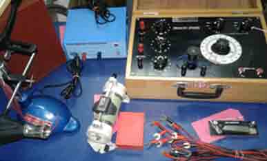
OSAW Industrial Kelvin Double Bridge Setup
Technical Specifications:
(i) OSAW Industrial Kelvin Doble bridge
(ii) DC Power Supply 15V/10A
(iii)Spot Galvanometer
(iv) One meter attachment
(v) Instructional Manual
(vi) Necessary Connecting leads
|
|
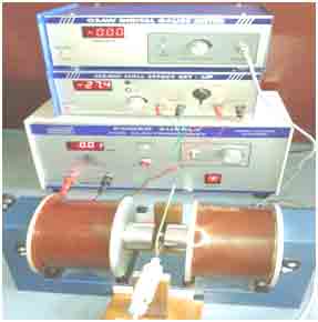
| 2 |
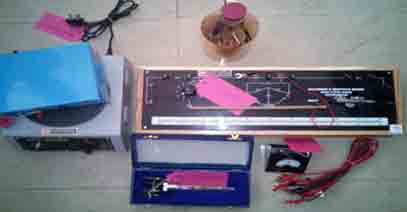
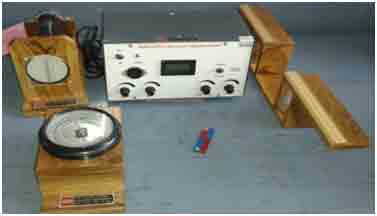
Temperature Coefficient of PRT
Experiment: To determine the temperature co-efficient of resistance for Platinum using Resistance
thermometer and Callender and Griffith’s Bridge.
Technical Specifications:
(i) Callender and Griffith Bridge
(ii) Platinum Resistance Thermometer(PRT)
(iii) Galavanometer(30 – 0 – 30) big size600µA
(iv)Hypsometer
(v) Battery Eliminator or Constant Voltage Source(2V/100mA)
(vi)Thermometer (110°C)
(vii) Patch Cords
(viii) Hot Plate
|
|
| 3 |
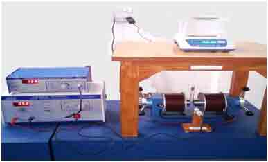
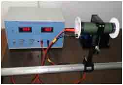
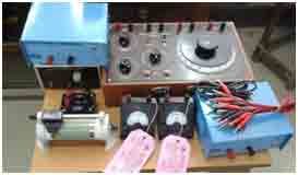
GOUY’S METHOD APPARATUS
Experiment:- To determine the susceptibility of a solid.
Technical Specifications:
1. Electromagnet 10 K Gauss.
2. Power supply for Electromagnet (0-8Amp)
3. Digital Gauss meter ( 0-20K Gauss)
4. Gauss Probe with stand
5. Digital Weighing Balance (with hook arrangement under it)
6. Wooden Base for Weighing Balance
7. Specimen – Ebonite Rod (cylindrical) Length – 12 cm , Dia – 1.17 cm
8. Aluminium test sample
9. Glass tube with cork & thread roll
|
|
| 4 |
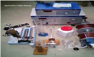
Quinck&;s Tube Method Setup
Experiment: Measurement of Magnetic Susceptibility of Paramagnetic Solution
(Liquid) by Quinck's Tube Method .
Technical Specifications:
(i) Quinck's tube with wooden stand
(ii) Sample : FeCl3 or MnSo4 + H2O
(iii) Beakers: Graduated 500ml ,1000ml
(iv) Measuring cylinder graduated 250ml
(v) ) Electronic Balance
(vi H&V Travelling Microscope
(vii) Electromagnet (7.5KG)
(viii) Constant Current Power Supply 35V/6A
(ix) Digital Gauss meter with Gauss Probe
(x) Filter paper 5sets
|
|
| 5 |
Rayleigh’s Bridge Setup
Experiment: Measurement of a unknown self inductance using Rayleigh’s Bridge.
Technical Specifications:
(i) Rayleigh’s Bridge
(ii) Constant Voltage Source
(iii) Ballistic Galvanometer
(iv) Lamp and Scale arrangement,
(v) Decade Inductance box(0.001H, 0.01H)
(vi) Taping Key
(vii)Unknown Inductances(1mH to 100mH)
(viii)Stop Watch
(ix) Rheostat
(x) Connecting leads
(xi) Instructional Manual
|
|
| 6 |
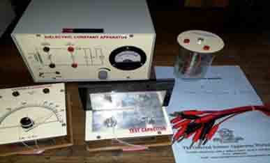
Dielectric Constant of Solid and Liquid Setup
Technical Specifications:
(i) Dielectric Constant Apparatus
(ii) Variable Gang capacitor
(iii) Test Capacitor for Solid
(iv) Test Capacitor for Liquid
(v) Dielectric Material
(vi) Connecting leads
(vii) Instructional Manual
|
|
| 7 |
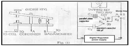
Dielectric constant using B.G.
Experiment: - determination of dielectric constant uses parallel plate capacitor and ballistic galvanometer (B.G.).
Technical Specifications:-
- Ballistic Galvanometer. (115 ohm.).
- Lamp and scale arrangement.
- DC regulated Power supply (0-30) volt. / 3 Amp.
- Fixed capacitor- 100 pf.
- Parallel plate capacitor. (60 pf. - 1000 pf.
- Tapping key-1.
- Morse key-1.
- Two way key-1.
- Samples of dielectric material as per size of the plates of parallel plate capacitor.
- Acrylic. b. Wood. c. Rubber
- Connecting leads.
- Manual.
|
|
| 8 |
OSAW Coupling Co-efficient of Piezoelectric Crystal Apparatus
Experiment :- To determine the coupling co-efficient of piezoelectric crystal .
Technical Specifications:
- Piezoelectric crystal, five no. crystal of standard value mounted inside a box
- Resistance box 10- 100 ohm
- Inductance Box 10- 100 mH
- Capacitance Box 1nF- 10nF
- AC Voltmeter 0-10 V and AC Current Meter 0-5 mA
- Frequency Source 1 Hz- 3 MHz
- Supplied with Patch Cords
- Instruction manual
|
|
| 9 |
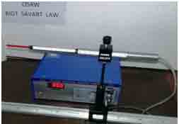
OSAW Biot -Savart law Apparatus
Experiment :-To study the Biot - Savart law and to calculate magnetic parameters.
Apparatus required:-
- Power Supply : 0-30V/5A D.C
- Gauss meter 0-2kG and 0-20kG
- Gauss probe with stand
- Aluminium alloy optical bench (hexagonal section type) having 100cm Scale and 1mm least count
- Solenoid holder arrangement
- Set of coils: with different diameter(30,40,50 and 80mm)
|
|
| 10 |
OSAW High Resistance Measurement By Leakage Method
Experiment: Measurement of High Resistance by method of leakage of a condenser.
Technical Specifications:
(i) Ballistic Galvanometer(115O)
(ii)Lamp & Scale arrangement
(iii)Tapping key
(iv)Morse key
(v)Fixed Condenser(1µ F)
(vi)High Resistance(40MO)
(vii)Rheostat (100O/1.2 Amp)
(viii)S.P.D.T Switch
(ix)Constant Voltage Source(2V/100mA)
(x) Stop Watch
|
|
| 11 |
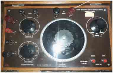
Calibration Of Voltmeter using Crompton Potentiometer
Experiment: Calibration Of Voltmeter using Crompton Potentiometer
Technical Specifications:
(i) Crompton Potentiometer
(ii)Constant Voltage Source (2V/100m Amp) -2Nos.
(iii)Electronic Standard Cell (1.0186V)
(iv)Galvanometer (30-0-30,600µA ,60O)
(v) Rheostat (110O/1.2Amp)
(vi)Voltmeter (0 -2V)
(vii)Connecting Leads---14Nos.
|
|
| 12 |
Calibration Of Ammeter using Crompton Potentiometer
Experiment: Calibration Of Ammeter using Crompton Potentiometer.
Technical Specifications:
(i) Crompton Potentiometer
(ii) Constant Voltage Surce (2V/100mA)
(ii)Regulated Power Supply(2V/1.5 Amp)
(iii)Electronic Standard Cell(1.0186V)
(iv) DC Galvanometer(30-0-30 ,600µA ,60O)
(v) Rheostat(20O / 2Amp)
(vi)DC Ammeter(0 -1Amp)
(vii) Shunt Resistance 1O (29574)
(vii)Connecting Leads
|
|
| 13 |
Hall Effect Setup(Semiconductor)
Technical Specifications:
1)Electromagnet 7.5 KG at 10mm gap between the pole pieces. Dia of pole pieces=75mm.
2)Digital power supply for electromagnet
Current : Smoothly adjustable from 0 to 3.5 A per coil i.e. 7A.
3) Digital Gaussmeter:
Range : 0-2K gauss and 0-20 K gauss.
Resolution : 1 gauss at 0-2K gauss range.
Accuracy: ± 5 %.
Display : 3 &1/2 digit 7 segment LED display.
Detector : Gauss probe
Power : 220 V,50 Hz.
4) Osaw Digital hall effect set-up or Composite Voltage- current source :
(a) Millvoltmeter : Range : (0-200 mV) and (0-2000 mV) selectable with selector
switch as provided on the front panel .
Resolution: 100µV. Accuracy : 0.1 % of reading ± 1 digit. Iimpedence : 1Mohm.
(b.) Current source :
Current range : (0-20 mA) selectable with selector switch an adj.current knob given on the
front panel of the apparatus.
Resolution: 10 µA.
Accuracy : ± 0.2% of the reading ± 1digit.
Load regulation : 0.03% for 0 to full load.
5) Hall probe :-
Ge crystal n & p type:- Ge-crystal with four spring type pressure contacts is mounted on the Glass Epoxy Circuit board. Four leads are provided for connection wit measuring Devices.
Hall voltage :- 0.1 -1 volt /100 mA/KG.
Thickness of Ge crystal : 0.4-0.5 mm.
Resistivity : approx. 10 O cm.
6) Hall probe or Gauss probe:-
Indium Arsenide crystal (rectagular) is mounted on a phenolic stripwith four soldered contacts for connections with measuring devices . The whole system is mounted in a pen type case for further protection ..
Contacts : soldered . Hall voltage : 8-10 mV/100 mA/KG.
Thickness and resistivity of the gauss sample not standard it may vary from probe to probe.
|
|
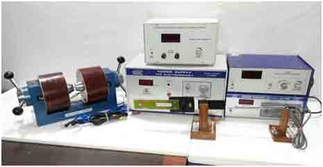
| 14 |
Hall Effect in Metals
Technical Specifications:
(1)Electromagnet 18KG
(ii)Electromagnet Power Supply 30V/10A
(iii) Digital Gauss Meter(200G)
(iv) Gauss Probe with wooden stand
(v)Hall Effect Setup
(vi)Hall probe with wooden stand
(vii)Sample : Silver(length= 8mm, breadth=5mm ,thicknes- 1mm)
(viii) Digital microvoltmeter
|
|
| 15 |
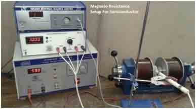
Magneto-resistance of Semiconductor Setup
Experiment : Measurement of Magneto-resistance of a Semiconductor
Technical Specifications: The Complete setup consists of the following:
(i) Magneto-resistance setup
(ii) Four Probe Arrangement
(iii) Sample : Highly doped Ge Crystal ( P-Type)
(iv) Electromagnet(7.5KG at 10mm gap between the ploe pieces of dia 75mm)
(v) Power supply for electromagnet(35V/6A)
(vi) Digital Gauss meter (0-2KG and 0-20KG) with Gauss Probe
(vii) Connecting leads
|
|
| 16 |
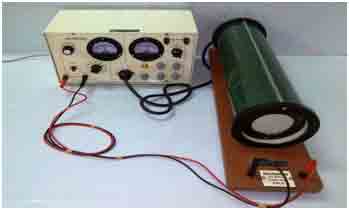
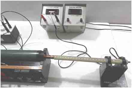
e/m Helical Method
Experiment: Measurement of e/m by Helical Method.
Technical Specifications:
(i) A Cathode ray tube
(ii) A Solenoid of proper dimension in the interior of which a cathode ray tube can be placed.
(iii) A Power supply that consists of the following controls on the front panel:
(a)Power supply to operate the CRT
(b) Power supply to operate the solenoid with variable fine control of voltage
(c) All necessary controls for Intensity, Focusing,X&Y Shift and deflection voltage
(d) Analog Voltmeter(1KVolts) and Ammeter(1A) are also provided
(iv) Connecting Leads
(v) Instruction Manual
|
|
| 17 |
e/m BY THOMSON METHOD (BAR MEGNET METHOD)
Experiment :- To determine the value of specific charge e/m of an electron by Thomson method.
Apparatus :
- Cathode Ray Tube (CRT) is mounted on wooden stand
- Power supply, fitted with a voltmeter to measure the deflecting voltage
- Bar magnet (Permanent) one pair
- Compass box one set
- Wooden stand having two arms fitted with scale to measure the distance of the poles of the magnets. The stand can accommodate cathode ray to be in its middle
- Another wooden stand is also provided to place the compass box in the centre. This wooden stand also be mounted in the middle of the armed stand.
|
|
| 18 |
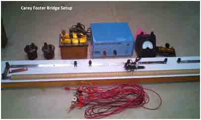
Carey Foster bridge setup
Experiment: To find the low resistance by Carey Foster Bridge
Technical Specifications:
(i)Carey Foster Bridge with Jockey
(ii)Thick Copper Strips –2Nos.
(iii)A fractional resistance box(0.1O - 1O) (29032)
(iv)Constant Voltage Source(2V/100mA)
(v)Galvanometer with Stand(30-0-30) (28038)
(vi)Resistance Coil (10 O)
(vii)One Way Plug Key
(viii)Unknown Resistance(0.001O)
(ix)Connecting Leads
(x) Instruction manual
|
|
| 19 |
Magnetic Field Through a Solenoid with AC Supply
Experiment:To study magnetic field through a solenoid using a search coil and an AC Source.
Technical specifications:
- A closely wound Solenoid having three layers of windings of different Turns with wooden stand
- A Search Coil(Pick-up coil) having few thousand turns with wooden stand
- Variable AC Supply 20V/2A
- Digital AC Ammeter
- Digital AC Voltmeter
|
|
| 20 |
Ammeter Calibration Using DC Slide Wire Potentiometer Setup
Technical Specifications:
- DC Slide wire potentiometer
- Constant voltage source (2V/100mA)
- Regulated DC Power Supply(0-2V/1.5A)
- Standard Cell( 1.0186V)
- Galvanometer (30-0-30,600µA, 60O)
- Ammeter(1A)
- Rheostat(20O/2A)
- Standard Resistance(29574) -1O
- Connecting leads
|
|
| 21 |
High Resistance by Substitution method
Experiment: Measurement of High resistance by Substitution Method.
Technical Specifications:
- (1)Resistance Box (1 -10000O)
- (2)Resistance Box (1 -5000O)
- (3)Unknown Resistance Coil 10 KO
- (4)Constant voltage source 2V/100mA
- (5)Galvanometer (30-0-30 ,600µA,60O)
- (6)One Way Plug key
- (7)Two Way Plug Key
- (8)Connecting Leads
|
| 22 |
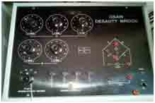
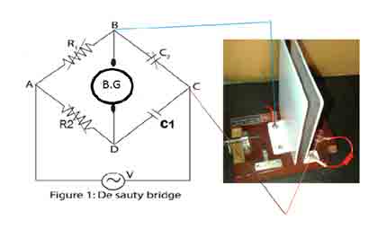
OSAW De-Sauty’s Bridge Apparatus
Experiment: Measurement of an Unknown Capacitance using De-Sauty Bridge.
Technical Specifications:
- OSAW De-sauty’s bridge trainer Kit consists of:
- (1)Three Decade resistance Dials R1 (10×1000O , 10×100O , 10×10O).
- (2)Three Decade resistance Dials R2 (10×1000O , 10×100O , 10×10O).
- (3)Two Fixed Standard Capacitors C1(0.1µF and 0.2µF) Loss Free
- (4)unknown inductances C2
- (5)Inbuilt AC Supplyr of 1Khz Frequency
- (6)Head phone as a Null detector
- (7)Connecting Leads
|
|
| 23 |
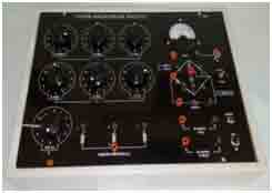
OSAW Anderson Bridge Apparatus
Experiment: Measurement of an Unknown Self Inductance using Anderson Bridge.
Technical Specifications:
- OSAW Anderson bridge trainer Kit consists of:
- (1)Three Decade resistance Dials R (10×100O , 10×10O , 10×1O).
- (2)Three Decade resistance Dials r (10×1000O , 10×100O , 10×10O).
- (3)Single Decade resistance Dials S (10×0.1O)
- (4)Two fixed standard capacitors having value 0.1µF and 0.2µF (Loss Free)
- (5)Inbuilt A.C Supply of 1Khz Frquency
- (6)Inbuilt DC Supply + 6Volts
- (7)Three unknown inductances
- (8)Head phone / Galvanometer(Analog or Digital) as a Null detector
- (9)Connecting Leads
- (10)Instructional Manual
|
|
| 24 |
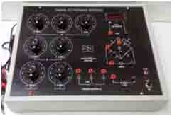
OSAW Schering Bridge Apparatus
Experiment: Measurement of an Unknown Capacitance using Schering Bridge.
Technical Specifications:
- OSAW Schering bridge trainer Kit consists of:
- (1)Three Decade resistance Dials R1 (10×1000O , 10×100O , 10×10O)
- (2)Three Decade resistance Dials R2 (10×1000O , 10×100O , 10×10O)
- (3)Single decade resistance dial R(10×100O)
- (4)Inbuilt A.F generator of 1Khz
- (5)Unknown Capacitances
- (6)Fixed Standard Capacitance C1(0.01µF loss free)
- (7)Two Decade Capacitance dials C2 having value ×0.001µF and ×0.0001µF
- (8)Head phone or digital meter as a null detector
- (9)Connecting Leads
- (10Instructional Manual
|
|
| 25 |
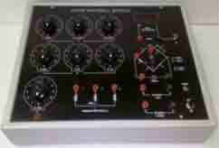
OSAW Maxwell bridge Apparatus
Experiment: Measurement of Self Inductance using Maxwell Bridge.
Technical Specifications:
- OSAW Maxwell bridge trainer Kit that consists of:
- Three Decade resistance Dials ‘R’ (10×100O , 10×10O ,10×1O )
- Three Decade Capacitance dials ‘C ‘ having value ×1µF , ×0.1µF and ×0.01µF
- P = Q --- Fixed Standard resistance having value 1000O.
- S --- Single decade resistance dial having value 10 × 0.1O)
- Inbuilt A.F generator of 1Khz
- Unknown Inductances
- Inbuilt DC Supply of +6Volts
- Head phone or digital meter as a null detector
- Connecting Leads
- Instructional Manual
|
|
| 26 |
OSAW Wein’s Capacitance Bridge Apparatus
Experiment: Measurement of an Unknown Capacitance using Wein’s Capacitance Bridge.
Technical Specifications:
- OSAW Wein’s Capacitance bridge trainer Kit consists of:
- Three Decade resistance Dials ‘P’ (10×100O , 10×10O ,10×1O )
- Three Decade resistance Dials ‘Q’ (10×100O , 10×10O ,10×1O )
- Two Decade resistance Dials ‘R’ (10×10KO , 10×1KO)
- Unknown resistance RX.
- Unknown Capacitance CX.
- Fixed Standard Capacitor C1 having value 0.01µF(Loss fee)
- Inbuilt A.C Supply of 1Khz frequency
- Unknown Inductances
- Head phone as a null detector
- Connecting Leads
|
|
| 27 |
Current Senitivity of B.G
Experiment: To Determine current sensitivity of B.G.
Technical Specifications:
- Ballistic Galvanometer
- ShuntResistance box(0.1O)
- Shunt Resistance Wire(0.1O) with out box
- Tapping key
- Resistance box (1- 1000 ohm)
- One way plug key
- Reversing key
- Lamp & scale
- Constant voltage source(2V/100mA)
- Connecting Leads-12Nos.
- Stop watch
- Instructional Lab Manual
|
|
| 28 |
To calibrate a thermocouple to measure temperature in a specified Range using
(i) Null Method,
(ii) Direct measurement using Op-Amp difference amplifier and to determine Neutral Temperature.
Technical Specifications:
This experimental setup consists of:
(i) Potentiometer 10 Wire
(ii)Electronic Standard cell
(iii)Copper-Constantan Thermocouple
(iv) Resistance box 1-1000ohm
(v)Rheostat 1500O/0.6A
(vi)Constant Voltage source2V/100 mA
(vii)One Way Plug key
(viii)Two Way plug Key
(ix)Two Hypsometers for hot and cold water
(x)Hot plate and Retort Stand
(xi)Operational amplifier trainer kit
(xii)Connecting leads
(xiii)Instruction Lab Manual
|
| 29 |
Di-electric constant(solid) using B.G. and de-Sauty bridge
Experiment: To calculate the di-electric constant of dielectric material (solid) by parallel plate capacitor, using de-sauty bridge and ballistic galvanometer.
Technical Specifications:
- Parallel plate capacitor
- De-sauty bridge : Main features of the apparatus are as given below
- R1-three decade resistance dials having values 10× 1000?, 10 ×100?, and 10× 10?
- R2-Three more decades of same values.
- C2-Unknown capacitor, four nos. Nos. of capacitors built in the apparatus and connections
- brought out on the panel with the help of 4mm. sockets . And a parallel plate capacitor externally given to measure the Di-electric constant of a Di-electric material.
- C1-two fixed standard capacitors having value: 0.1µf & 100pf (loss free)
- Test samples of Di electric material- acrylic, wood, glass etc.
- Connecting wires
- Inbuilt A.C. supply of frequency 1 KHz and four Nos. unknown capacitors are provided which may be used to perform the experiment.
- 4 mm. sockets are provided for external or internal connections to connect the unknown capacitor, A.C. supply or capacitor.
- Parallel plate capacitor(0-500pf.)
|
|
| 30 |
To study the variation of thermo EMF of a Thermocouple with Difference of Temperature of its Two Junctions.
Technical Specifications:
- Ten wire potentiometer
- Copper constantan thermocouple
- Galvanometer(28038) - (30-0-30)
- Rheostate 1500 ohm / 0.6 amp
- One way key
- Two way key
- Thermometer 3600 C
- Electric standard cell (1.018V)
- Hot plate
- Constant voltage source (2 Volts /100 milliAmpere)
- Resistance box 1- 10000 ohm
- Connecting leads
- Retort stand
- Hypsometers -2 Nos.
- Instructional Lab Manual
|
|
| 31 |
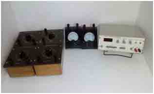
Measurement or Comparision of Low Resistance Using Crompton Potentiometer
Technical Specifications:
- Crompton Potentiometer
- Electronic Standard Cell(1.0186V)
- Constant Voltage Source(2V/100mA)
- Galvanometer(30-0-30 ,600µA,60O)
- Standard Resistance 1O -----2Nos.
- DC Regulated Variable Power Supply (0-6V/1.5A)
- Rheostat(20O/2A)
- Ammeter(1A)
- Connecting Leads
|
|
32 |
Measurement of field strength B and is variation with distance using search coil
Technical Specifications:
- Power supply 10 volt /0-3 amp
- B.G
- Lamp & scale
- Solenoid with scale
- Search coil(150-Turns ,Dia 2.5cm ,Resistance 3.5ohm)
- Reversing key
- One way key
- Ammeter 0-3 amp
- Rheostate 20 ohm /5 amp
- Connecting Leads
- Tapping key
- Retort stand
- Instructional lab manual
|
|
33 |
To determine the Ballistic Reduction Factor(Ballistic Constant) ‘K’ by Steady Deflection Method
Technical Specifications:
- A Ballistic Galvanometer
- Lamp and Scale arrangement
- A cell of Constant emf.
- Rheostat 100O
- Three resistance boxes
- One way key
- Tapping key
- Reversing Key
- Connecting wires
- Meter Rod
- Instructional Lab Manual
|
|
34 |
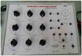
Student Kelvin Double Bridge
Measurement of unknown low resistance by using Student Kelvin Double Bridge.
Technical Specifications:
- Student Kelvin Double Bridge
- Unknown Low Resistance
- Super sensitive Galvanometer(Big Size)
- DC Source(0-5A)
- Conductivity Attachment(50Cm)
- Connecting leads
|
|
35 |
Ballistic Constant’K’ With Standard Condenser Of Known Capacity
To determine the Ballistic Constant’K’ of a moving coil galvanometer with standard capacitor of known capacity.
Technical Specifications:
(1)Ballistic Galvanometer(115O)
(2)Tapping key
(3)Rheostat(110O)
(4)Morse key
(5) Constant Voltage Source(2V/100mA)
(5)A Condenser of known capacity (2.2µF)Elcot.
(6)DC Voltmeter(0-2V)
(7) Lamp and Scale arrangement
(7)Connecting wires ---14 Nos.
|
|
36 |
Internal Resistance of Laclanche Cell using 10-Wire Potentiometer
To measure the Internal Resistance of a given Laclanche Cell using 10-Wire Potentiometer
Technical Specifications:
(1)10-Wire Potentiometer with Jockey
(2)DC Power Supply 2V/1A
(3)One Way Plug Key ---2Nos.
(4)Rheostat(110O/2A)
(5)Galvanometer-(30-0-30 ,600µA)
(6)RResistance Box Three Dial(×10O , ×100O , x1000O)
(7)Laclanche Cell
(8)Ammonium Chloride as an electrolyte
(9)Connecting Wires
|
|
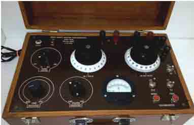
| 37 |
OSAW Industrial Kelvin Double Bridge
Range: 0.2 µO to 11 Ohms)
OSAW Kelvin Double Bridge have been designed for the convenient and accurate measurement of low resistances. These instruments are particularly useful for measurements of resistance of Transformers, Armature Windings, Quality Control of Electric Cables and wires, Temperature rise Test of Transformers and similar applications.
This bridge is Compact, Robust and Simple in operation and measurements to be carried out with highest attainable precision.
Technical Specifications:
- Variable Standard resistances : 10 steps of 0.01 O and one slide wire Dial of 0.01Odivided into 500 equal parts.
- Multiplier Dial : ( ×0.01, ×0.1, ×1, ×10, ×100)
- Battery Terminal : Two Battery Terminals marked on the panel for battery or DC Source connections.
- Galvano Terminals : Two Galvanometer terminals marked on the panel are used to connect the Highly sensitive Galvanometer.
- X-Terminals : Four terminals on the left hand side of the panel are used to connect the unknown resistance. Two inner terminals(P1 & P2) are potential terminals ,while Two outer terminals(C1 & C2 ) are Current terminals.
- Total Range : 0.2µO to 11O
- Accuracy : ±.05% of the measuring value or ±1 Slide Wire Division which ever is greater
- Current : 0-5A Continuously and 0-10A intermittently.
- Dimension : 410mm×260mm×160mm approx.
- Weight : 7Kg approx.
|
|
| 38 |
OSAW Direct Reading Potentiometer
|
|
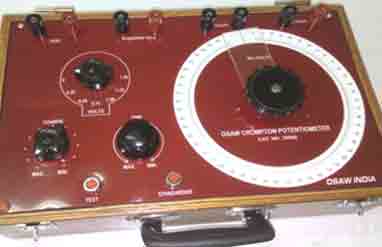
| 39 |
OSAW Crompton Potentiometer
|
|
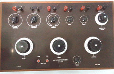
| 40 |
OSAW Vernier Potentiometer
|
|